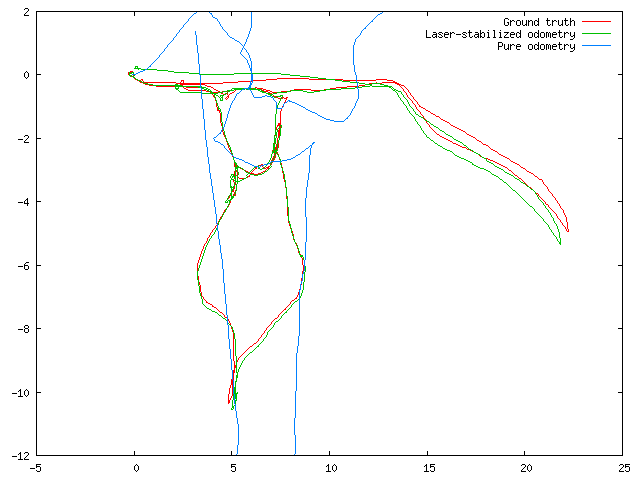
Trajectory plot: odometry versus laser-stabilized odometry
#include <gsl/gsl_min.h>
#include "slap.h"
Go to the source code of this file.
Classes | |
| struct | lodo_scan_t |
| Data pertaining to an individual scan. More... | |
| struct | lodo_map_point_t |
| Working data for a map point. More... | |
| struct | lodo_scan_point_t |
| Working data for scan point. More... | |
| struct | lodo_t |
| Laser odometry module data. More... | |
Defines | |
| #define | LODO_MAX_RANGES 401 |
| Limits. | |
Functions | |
| lodo_t * | lodo_alloc (int num_ranges, double range_max, double range_res, double range_start, double range_step) |
| Allocate object. | |
| void | lodo_free (lodo_t *self) |
| Free object. | |
| pose2_t | lodo_add_scan (lodo_t *self, pose2_t odom_pose, int num_ranges, double *ranges) |
| Add a scan, compute correction, update map. | |
| void | lodo_project_map (lodo_t *self) |
| Project map points into scan polar coordinates. | |
| void | lodo_project_map_free (lodo_t *self, lodo_scan_t *scan_m, matrix33_t Pd, matrix33_t Pm) |
| Project map free space into the scan polar frame. | |
| double | lodo_correct (lodo_t *self) |
| Compute correction for a scan. | |
| double | lodo_test_offset (lodo_t *self, double offset, double *outliers) |
| Test a scan offset. | |
| void | lodo_print_map (lodo_t *self) |
| Print projected map points. | |
| void | lodo_print_pef (lodo_t *self) |
| Print a polar error functions for scan and map. | |
| void | lodo_print_err (lodo_t *self) |
| Print error histograms. | |
| void | lodo_draw_scan (lodo_t *self, lodo_scan_t *scan) |
| Draw a scan. | |
| void | lodo_draw_map (lodo_t *self) |
| Draw the current map (hits). | |
The drift in the corrected estimate is much lower than that seen with odometry alone. See, for example, the figure below: this plot shows the trajectory of a robot that has travelled 125m and executed 19 complete rotations before returning to the starting location. The final cumulative orientation error is less than 5 degrees (versus 110 degrees for pure odometry).

Trajectory plot: odometry versus laser-stabilized odometry
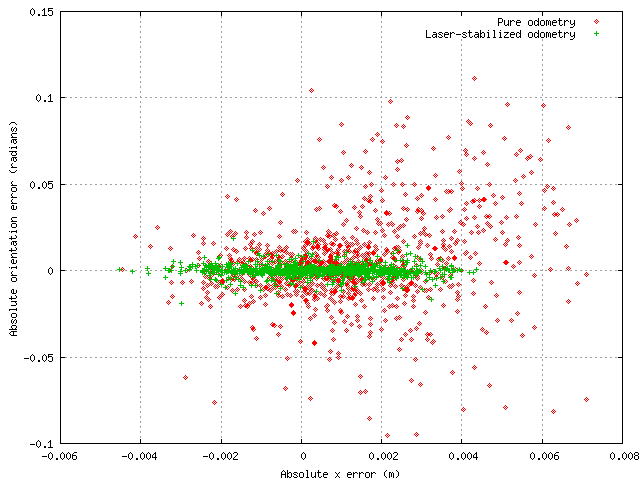
Absolute error plot: odometry versus laser-stabilized odometry
The algorithm applied to each new laser scan is as follows:
The intuition behind this algorithm is best explained in diagrams (below).
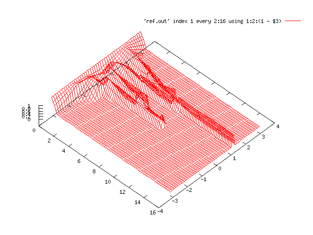
Figure (a) shows a map scan in global carestian coordinates; the map scan is projected into the coordinate frame of the new scan and converted to polar coordinates (b); using dynamic programming, we compute the error function (c). This polar error function can be used to test possible orientation corrections very efficiently: changes in the orientation of the new scan correspond the translations of the polar error function.
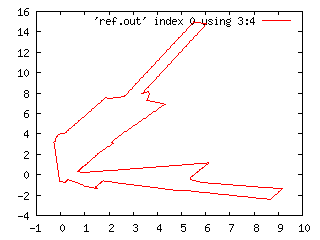
(a) Original map scan (cartesian coordinates). | 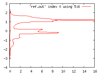
(b) Map scan in local polar coordinates. |
(c) Calculated polar error function. | |
|
||||||||||||||||||||||||
|
Allocate object.
|
|
||||||||||||||||||||
|
Add a scan, compute correction, update map.
|
|
|
Project map points into scan polar coordinates.
For internal use only.
|
|
||||||||||||||||||||
|
Project map free space into the scan polar frame.
For internal use only.
|
|
|
Compute correction for a scan.
For internal use only.
|
|
||||||||||||||||
|
Test a scan offset.
For internal use only.
|
 1.3.8
1.3.8