How to build your robot
Design files
Download design files
Includes bill of materials, STL files for 3D printed parts, and data sheets
Tools
- Cable Cutter
- Wire Cutter/Stripper
- Wire Crimper
- Multimeter
- Soldering Iron (390F)
- Zip Ties
- Hacksaw (to cut metal rods)
- Drill (for customizing power supply enclosure)

Build Power Supply Box
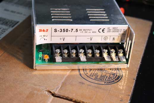
- Switch power supply (BOM line #1) to 115 V with tab on side
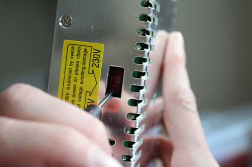
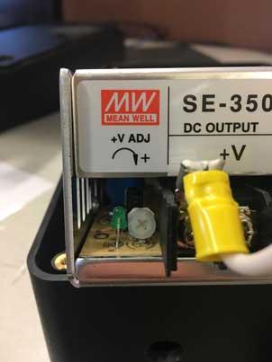
- Install quick connector rectangular tongue terminals (#49) on power supply
- Cut both plugs off of extension cord (NOT power cable, #8); cut two 5-6 inch pieces off cord and set aside remainder
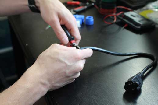
- Cut off outer coating and separate wires on each end of the two short pieces of extension cord
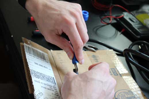
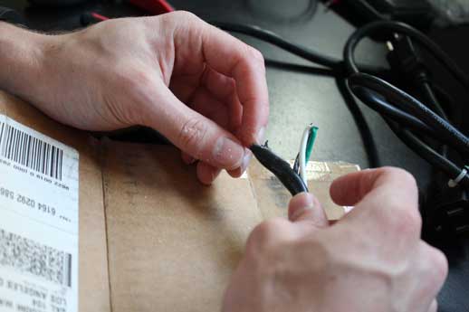
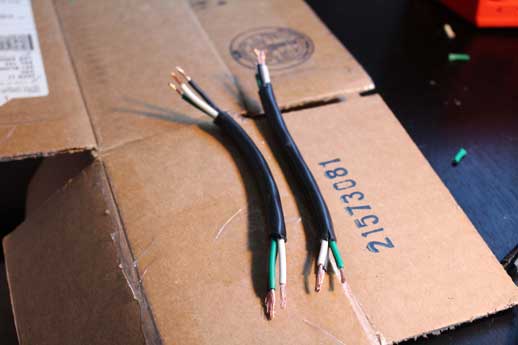
- Strip wires and install quick-disconnects (#48) to all wires on both ends of one short extension cord piece
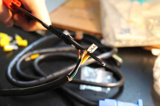
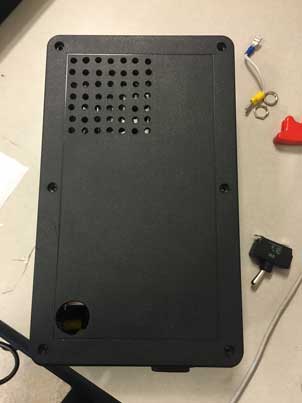
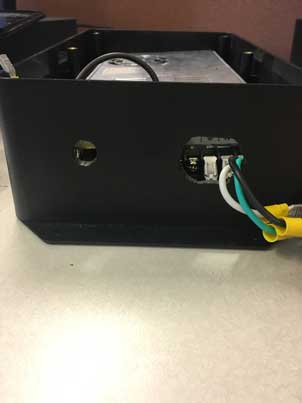
- Cut holes (see datasheets in design files download for cut-out size) in plastic enclosure (#42) for:
- Connect power supply (power-in, ground, neutral) to power plug socket
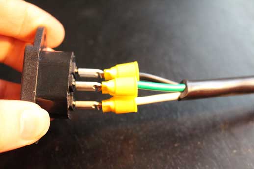
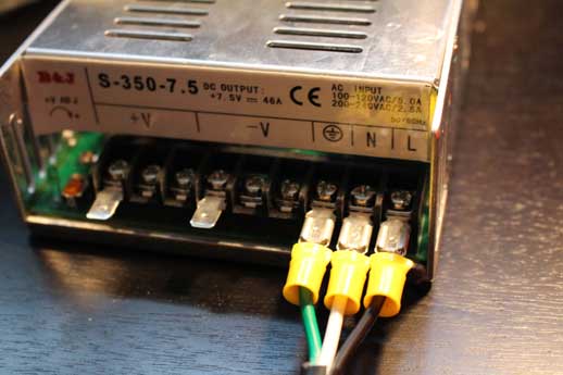
- Adjust voltage on power supply
- With other short extension cord piece:
- Discard ground wire
- Cut positive wires in roughly half
- Install yellow quick disconnects (#48) to both ends of positive (x2) and negative wires
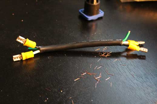
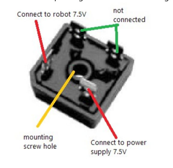
(can remove black coating entirely) - Connect one short positive wire from V+ out to the diode lead(see image), connect a wire from another diode lead (see image for correct diode leads) to the positive neutrik lead, the negative wire from V- output to the tab of the switch, and another wire from the other of the switch to the negative neutrik lead. (the switch can be oriented in the opposite direction of the picture below).
- Check switch orientation with multimeter (switch flipped up should be on, flipped down should be off)

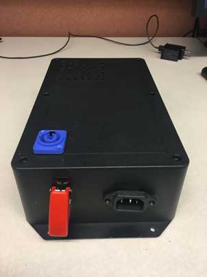
- Completed power supply box
Wire and Install Servos
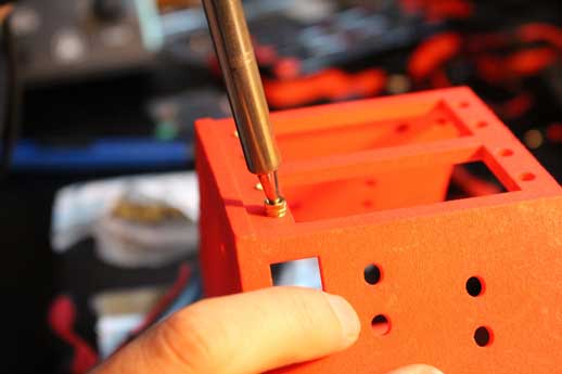
- Install heat-set inserts (#12 - MMC 93365A130 x24) into main housing box (#31 x1) with soldering iron
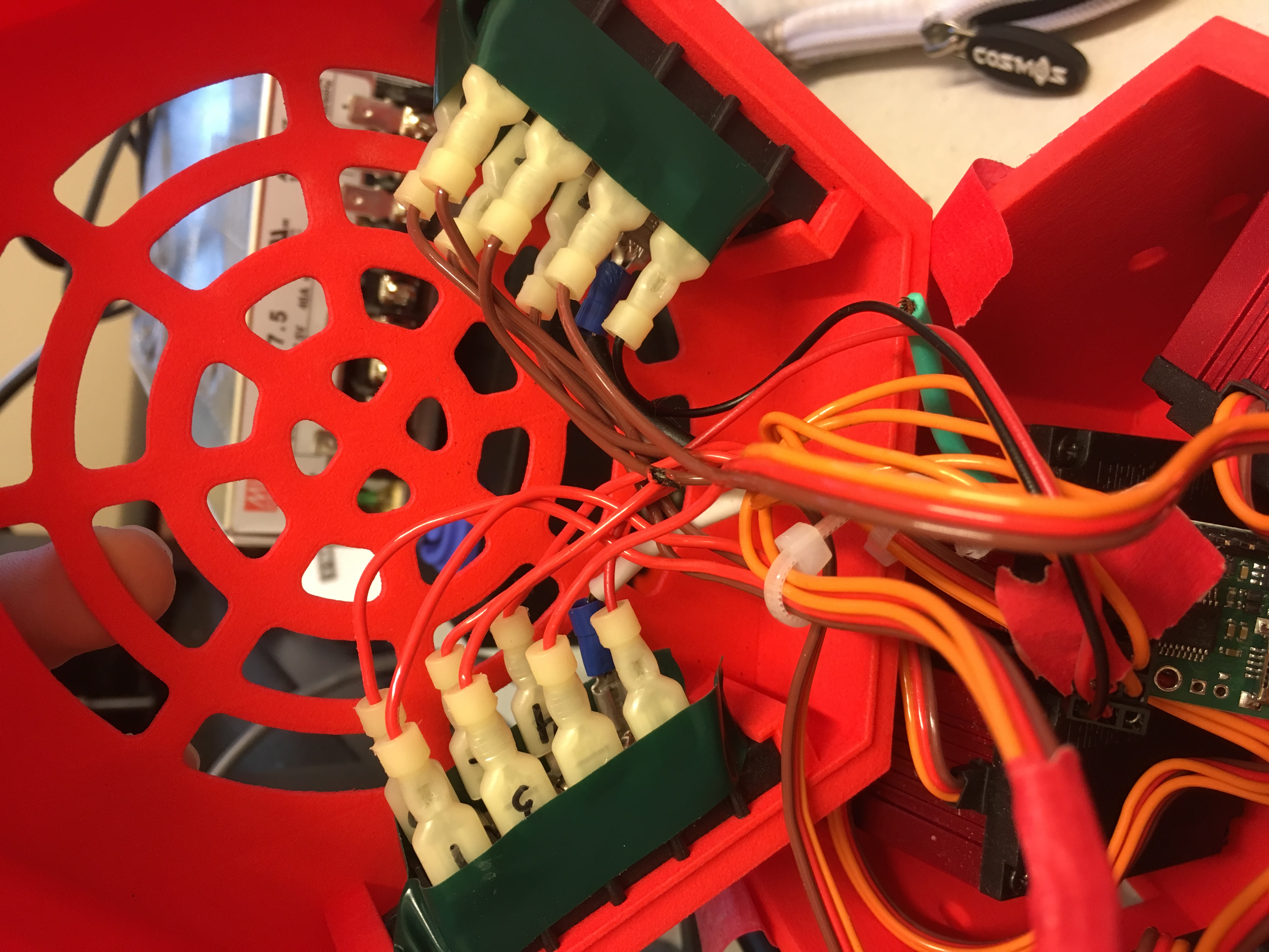
- Unscrew screws from terminal block (#4) and install jumper bars (#5) and quick-disconnect (#6) terminals (x2 terminal blocks)
- Slide terminal blocks into lid (#37)
- Separate and strip wires ~2” down each end of the long piece of extension cord leftover from making power supply
- Install Neutrik connector (#45) on one cord end (connector assembly instructions)
- Install blue (#47) quick disconnects to power and ground on other cord end; trim ground
- Cut power and ground wires to servos (#2); strip, and install quick-disconnect terminals (#10) to them
- See here to find out which wire goes where, do not cut the wrong wire!
- Note: twist strands before inserting into quick-disconnects
- Cut male pin end of servo extension cord (#7) and install quick disconnect terminals (#10)
- Install power and ground of modified servo extension cord and power cable to terminal blocks (pick one to be power, one to be ground)
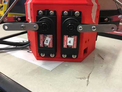
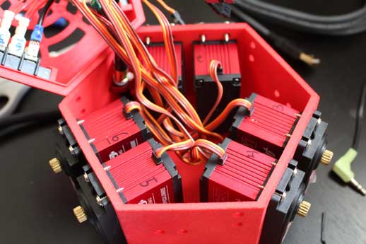
- Install servos into main box. Lightly tighten screws then cinch down in diagonal pattern.
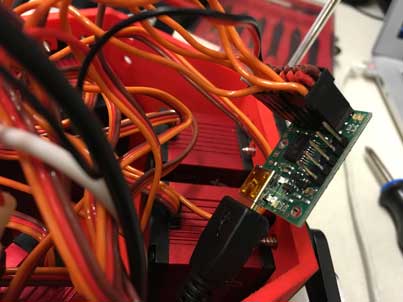
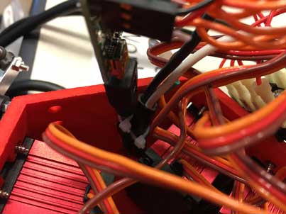
- Connect all power wires from servos to power terminal block/all ground wires to ground terminal block, and all pin heads to micro controller board (#3)
- Label motors and their connectors
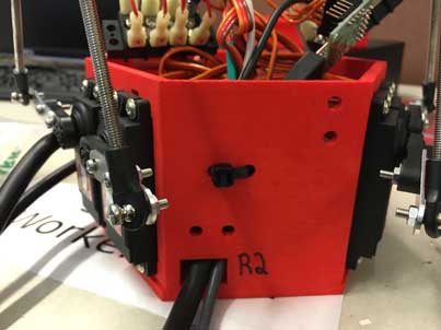
- Insert power cord and USB cable (#11, connected to microcontroller board) in hole in servo box to the right of motor 0
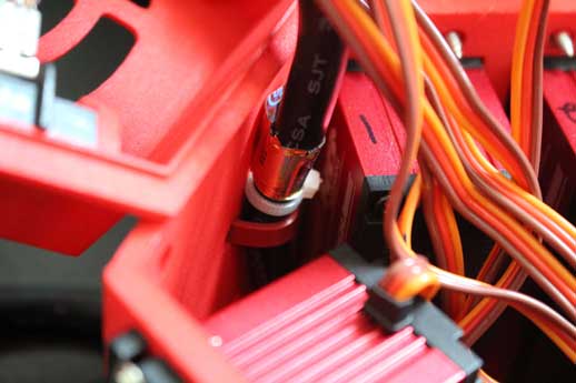
- Place a zip tie around power cord, use a second to tie cord to box below the first. Repeat with USB cable.
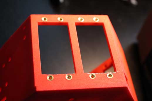
x3 sides
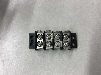
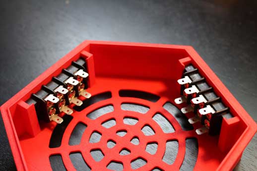
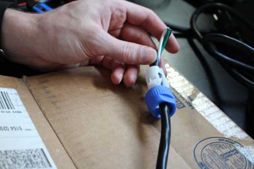
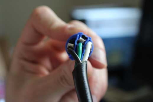
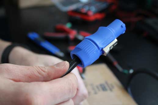
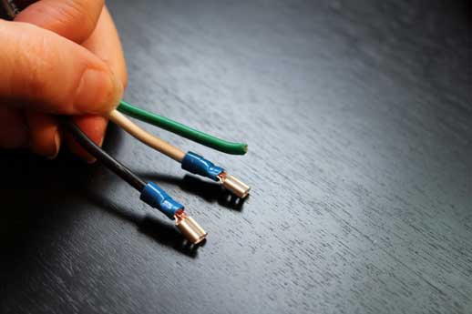
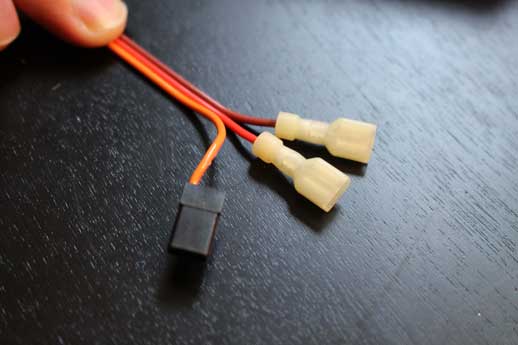
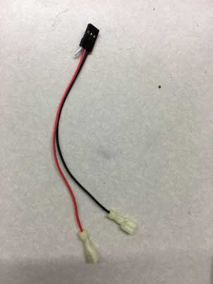
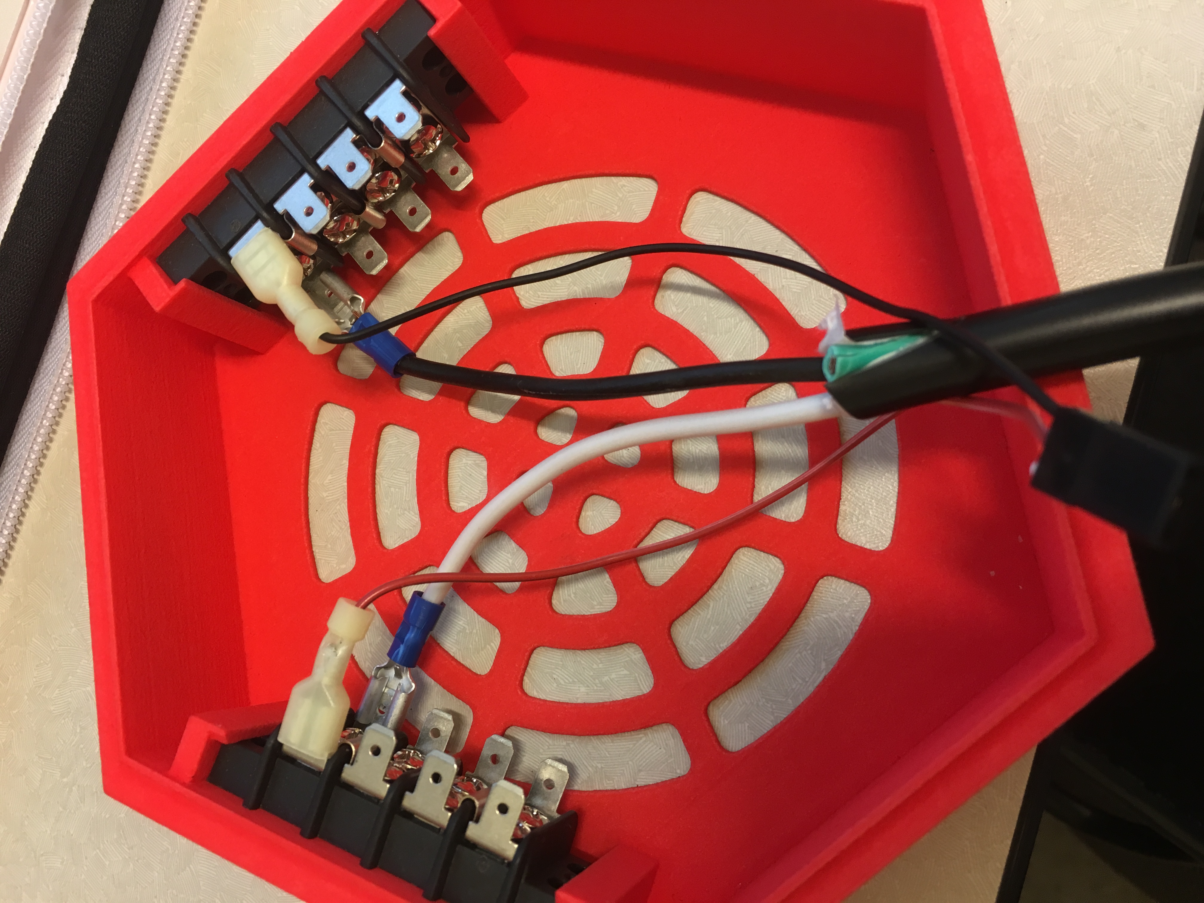
(may be easier to remove terminal blocks from lid to make these connections)
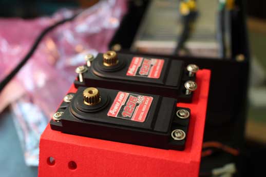
Install Servo Arms
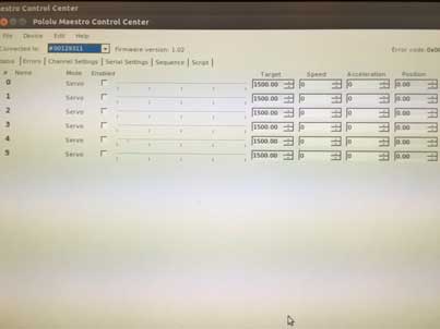
- Plug in system (robot to power supply, power supply to outlet, USB cord to computer) and run Maestro Control Center (download Maestro Servo Controller Linux Software here)
- Read the instructions in the readme, you will need to add a user to the "dialout group"
- Set board to "dual USB" in "Serial Mode" under "Serial Settings"
- Set all motors to 1500
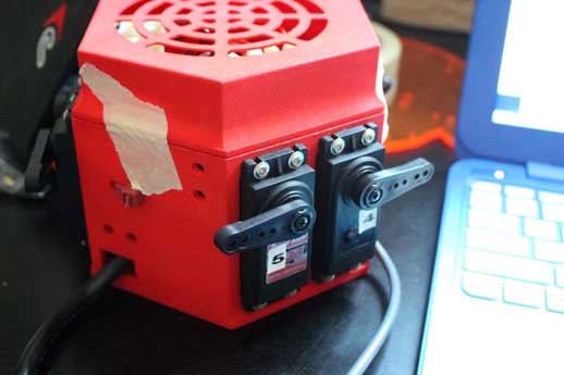
- Slide on servo arms (come with servo motor) at horizontal position, facing outwards; adjust motors by +/ 58.75 ticks (1441.25 or 1558.75) to make servo arms horizontal. Make note of which motors need adjustment.
- Loosely install screws for servo arms (black, plastic come with motors); unplug robot and tighten screws
- (Optional) Attach servo horn extenders
Final Assembly
- Cut metal 1m rod (#18) into six 15 cm pieces
- Attach traxxas rod ends (#13) to each end of 15 cm rods
- Assemble face plate - choose one option below
- Laser-cut top plate:
- Laser cut plate (#21 material, STL file in download above)
- Install heat set inserts (#12) in face plate (#40) and heat set inserts (#16) in 3Dprinted rod end brackets (#30)
- Attach rod end brackets to faceplate (#25 screws)
- 3D-printed top plate:
- 3D print plate (STL file in download above)
- Laser-cut top plate:
- Attach 15 cm rods to servo horns (#14 screw and #15 nut)
- Attach rods to top plate (#14 screw)
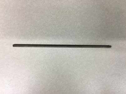
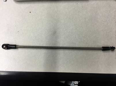
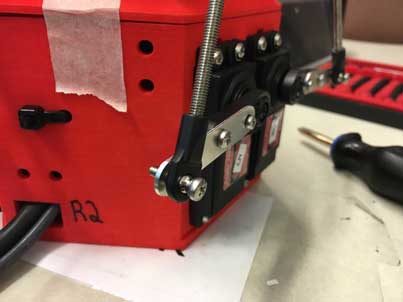
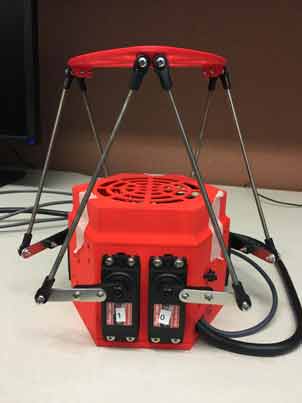
fully assembled robot without cranium/phone holder (shown with optional servo extenders and original top plate design)
Test
- Connect the neutrik connector from the robot to the power supply, plug in power supply to outlet, and connect USB from robot to computer. Run the robot using ROS, if the servos move/ power supply does not heat up then robot is complete.
